Coordinate System
QPainter 控制坐标系统. QPainter 与 QPaintDevice, QPaintEngine 一起构成Qt绘图系统基础. QPainter 用于绘图操作, QPaintDevice 是 QPainter 绘图的二维空间的抽象类, QPaintEngine 提供绘制不同类型设备的接口.
QPaintDevice 是可绘图对象的基类: 它的派生类有 QWidget, QImage, QPixmap, QPicture, 及 QOpenGLPaintDevice. 绘图设备的默认坐标系统的原点位于左上角. x 轴的增长方向向右, y 轴的增长方向向下. 默认单位: 像素设备是一个像素 打印设备是一个点(1/72英寸).
QPainter 逻辑坐标到 QPaintDevice 物理坐标的映射由 QPainter的变换矩阵, 视口和 "窗口"处理. 默认情况下, 逻辑坐标和物理坐标重合. QPainter 也支持坐标转换 (如. 旋转和缩放).
渲染
逻辑表示
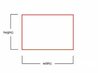
图元的大小 (宽高) 始终与数学模型对应, 渲染时忽略笔宽:
走样绘制
绘制时, 像素渲染被渲染标识(QPainter::Antialiasing) 控制.
RenderHint 标识 QPainter 引擎应该遵守或不遵守的绘图方式. QPainter::Antialiasing 值表示绘图引擎在可能的情况下, 即. 使用不同的颜色强度平滑图元边缘.
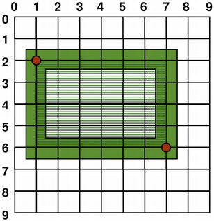
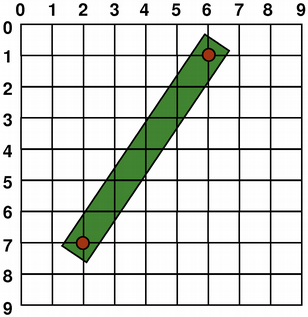
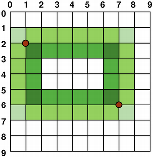
默认情况下, 绘制是 走样的, 其他规则也适用: 采用一像素笔宽绘制时, 像素自动绘制在数字点的右下方. 如:
 |  |
QPainter painter(this); painter.setPen(Qt::darkGreen); painter.drawRect(1, 2, 6, 4); | QPainter painter(this); painter.setPen(Qt::darkGreen); painter.drawLine(2, 7, 6, 1); |
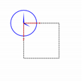
采用偶数像素绘制时, 像素将围绕数字点对称渲染; 采用奇数像素绘制时, 像素将绘制在数字点右下方, 类似一像素. 具体示例参见下图.
| QRectF | ||
|---|---|---|
 |  | |
| Logical representation | One pixel wide pen | |
 |  | |
| Two pixel wide pen | Three pixel wide pen | |
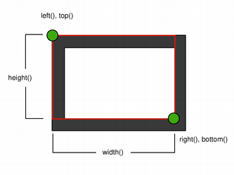
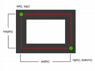
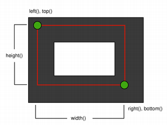
注意: 由于历史原因 QRect::right() 和 QRect::bottom() 函数返回值偏离矩形真正的右下角.
QRect的 right() 函数返回 left() + width() - 1. bottom() 函数返回 top() + height() - 1. 上图右下角的绿点显示这些函数的返回坐标.
我们建议你使用 QRectF: QRectF 使用浮点坐标定义平面矩形, 确保矩形的准确性 (QRect 采用整型), QRectF::right() 和 QRectF::bottom() 返回真正的右下角坐标.
或者, 使用 QRect 的 x() + width() 和 y() + height() 获取右下角坐标, 避免使用 right() 和 bottom().
反走样绘制
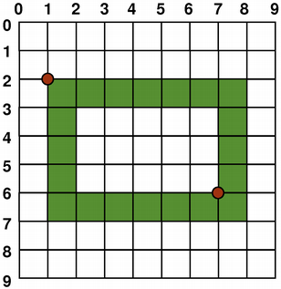
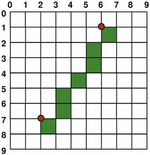
如果你设置 QPainter 的 anti-aliasing 标识, 像素将围绕数字点对称渲染:
 | 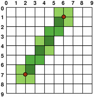 |
QPainter painter(this); painter.setRenderHint( QPainter::Antialiasing); painter.setPen(Qt::darkGreen); painter.drawRect(1, 2, 6, 4); | QPainter painter(this); painter.setRenderHint( QPainter::Antialiasing); painter.setPen(Qt::darkGreen); painter.drawLine(2, 7, 6, 1); |
变换
默认情况下, QPainter 在设备相关的坐标系操作, 但是, 它也支持仿射坐标变换.
你可以使用 QPainter::scale() 函数对坐标系缩放, 使用 QPainter::rotate() 函数顺时针旋转坐标系, 使用QPainter::translate() 函数平移坐标系.
你可以调用 QPainter::shear() 函数围绕原点扭曲坐标系. 所有的变换操作都是对 QPainter变换矩阵操作, 调用 QPainter::worldTransform() 函数获取矩阵. 矩阵将一个点转换为另一个点.
如果你需要反复进行相同的转换, 你也可以使用 QTransform, QPainter::worldTransform(), QPainter::setWorldTransform(). 你可以随时调用 QPainter::save() 保存 QPainter的转换矩阵, 矩阵保存在内部堆栈. 调用 QPainter::restore() 函数弹回矩阵.
转换矩阵常用场景是在绘图设备上重复使用相同的绘图代码. 没有转换矩阵时, 绘图结果与分辨率相关. 打印机具有高分辨率, 如. 如每英寸600点, 而屏幕通常每英寸72到100点.
| Analog Clock Example | |
|---|---|
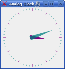 | The Analog Clock example shows how to draw the contents of a custom widget using QPainter's transformation matrix. We recommend compiling and running this example before you read any further. In particular, try resizing the window to different sizes. |
  void AnalogClockWindow::render(QPainter *p)
  {
      static const QPoint hourHand[3] = {
          QPoint(7, 8),
          QPoint(-7, 8),
          QPoint(0, -40)
      };
      static const QPoint minuteHand[3] = {
          QPoint(7, 8),
          QPoint(-7, 8),
          QPoint(0, -70)
      };

      QColor hourColor(127, 0, 127);
      QColor minuteColor(0, 127, 127, 191);

      p->setRenderHint(QPainter::Antialiasing);
      p->translate(width() / 2, height() / 2);

      int side = qMin(width(), height());
      p->scale(side / 200.0, side / 200.0);
We translate the coordinate system so that point (0, 0) is in the widget's center, instead of being at the top-left corner. We also scale the system by This will give us a 200 x 200 square area, with the origin (0, 0) in the center, that we can draw on. What we draw will show up in the largest possible square that will fit in the widget. See also the Window-Viewport Conversion section.
      QTime time = QTime::currentTime();

      p->save();
      p->rotate(30.0 * ((time.hour() + time.minute() / 60.0)));
      p->drawConvexPolygon(hourHand, 3);
      p->restore();
We draw the clock's hour hand by rotating the coordinate system and calling QPainter::drawConvexPolygon(). Thank's to the rotation, it's drawn pointed in the right direction. The polygon is specified as an array of alternating x, y values, stored in the The calls to QPainter::save() and QPainter::restore() surrounding the code guarantees that the code that follows won't be disturbed by the transformations we've used.
      p->save();
      p->rotate(6.0 * (time.minute() + time.second() / 60.0));
      p->drawConvexPolygon(minuteHand, 3);
      p->restore();
We do the same for the clock's minute hand, which is defined by the four points (1, 0), (0, 1), (-1, 0), and (0, -40). These coordinates specify a hand that is thinner and longer than the minute hand.
      p->setPen(minuteColor);

      for (int j = 0; j < 60; ++j) {
          if ((j % 5) != 0)
              p->drawLine(92, 0, 96, 0);
          p->rotate(6.0);
      }
Finally, we draw the clock face, which consists of twelve short lines at 30-degree intervals. At the end of that, the painter is rotated in a way which isn't very useful, but we're done with painting so that doesn't matter. | |
For more information about the transformation matrix, see the QTransform documentation.
窗口视口转换
若使用 QPainter绘制, 我们使用逻辑坐标绘制, 然后将其转换为绘图设备的物理坐标.
逻辑坐标到物理坐标的映射由 QPainter的 worldTransform() (详见 Transformations 章节), QPainter的 viewport() 和 window(). 视口表示任意矩形物理坐标. "窗口" 描述逻辑坐标中的相同矩形. 默认情况下, 逻辑坐标和物理坐标重合, 相当于绘制设备的矩形.
使用窗口视口转换可以使逻辑坐标系符合你的偏好. 这个机制也可用于与绘图设备无关的绘制代码. 你可以调用QPainter::setWindow()函数将逻辑坐标从 (-50, -50) 到 (50, 50), 中心坐标为 (0, 0):
  QPainter painter(this);
  painter.setWindow(QRect(-50, -50, 100, 100));
现在, 逻辑坐标 (-50,-50) 对应绘图设备的物理坐标 (0, 0). 你的绘制代码与设备无关, 始终在特定的逻辑坐标操作.
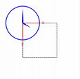
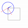
你可以设置 "窗口" 的每个角都映射到视口对应的角. 因此, 保持视口和 "窗口" 相同的纵横比以防止变形是一个好方式:
  int side = qMin(width(), height())
  int x = (width() - side / 2);
  int y = (height() - side / 2);

  painter.setViewport(x, y, side, side);
如果逻辑坐标是一个正方形, 我们应该调用 QPainter::setViewport() 函数将视口设为正方形. 上述示例, 我们将其设置为适应绘制设备的最大正方形. 在窗口或视口考虑绘制设备的大小, 可以使绘图代码独立于绘制设备.
注意: 窗口视口变换是一种线性变换, 即. 它不执行剪裁. 这意味着, 若在当前 "窗口"之外绘制, 绘制仍将使用相同的线性代数转换到视口.
![]()
视口, "窗口" 和变换矩阵决定如何将 QPainter 逻辑坐标映射到绘制设备的物理坐标. 默认情况下, 世界变换矩阵是单位矩阵, 设置"窗口"和视口等效于设置绘制设备, 即. 世界, "窗口" 和设备坐标等效, 但是, 正如我们所看到, 可以使用变换操作和窗口视图转换操作系统. 上图描述这一过程.